|
Building a breakout with ISP for an Arduino Pro-Mini
The Arduino Pro-Mini is a great little microcontroller board for all sorts of applications. It is tiny so it can go where larger boards can't. It's cheap enough to sprinkle around wherever you need one. It is very low power and the current consumption can be reduced even further by removing the power LED and the voltage regulator.
I have plans to use these things for a lot of battery operated gadgets and things that need to be really small. They are also cheap enough to use in place of discrete components for incorporating into larger pieces of equipment.
You can build the breakout board right into your project or if space is a premium then you can program the Pro-Mini on the carrier then unplug it and plug into your project board. For programming you can either use an ArduinoISP board or you can use an Arduino UNO as an ISP for programming.
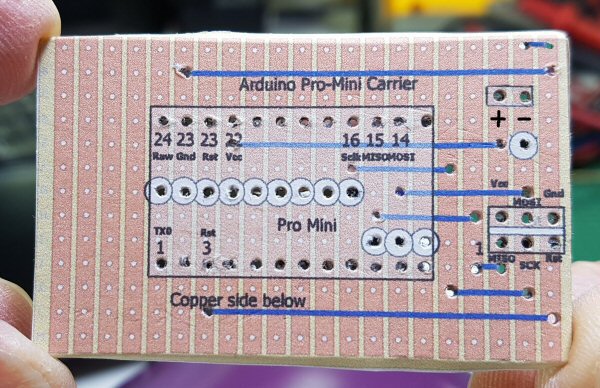
Layout for the Pro-Mini Carrier Breakout
You can download a PDF with the above layout from here: Arduino Pro-Mini carrier layout. The layout in the link is a later version than shown above. The difference being that some of the Pro Mini pins are broken out for a later project. These breakouts can be ignored if you don't need them.
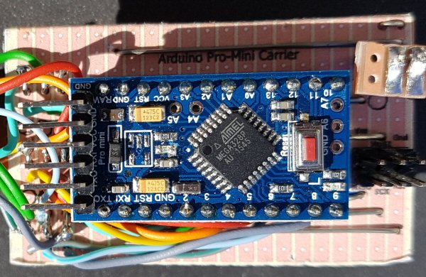
By printing the layout full size with no scaling you should be able to match the layout to a piece of Veroboard like in the image above. This helps a lot with construction and remembering what does what. Notice that the blue lines are wire links and the white circles are where you should cut the copper tracks.
Cut the tracks and insert the components
You can cut the tracks where the white circles are using a 6mm drill bit then insert the links and pin headers. Solder the terminals on the underside of the board taking care to make sure that the pin headers are perpendicular to the board after soldering. A trick to doing this is to solder only one pin of each header strip then turn the board over and heat up the joint while pushing the header into place before soldering the remaining pins.
Making an ISP programming cable
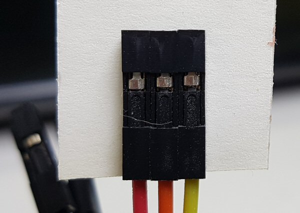
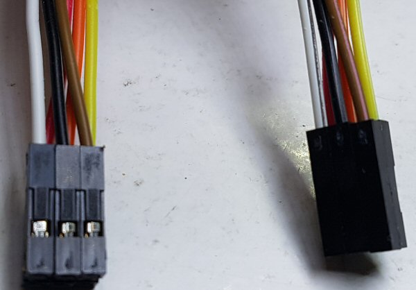
An ISP cable is made up of 6 wires arranged on the connectors one to one in two rows of three pins. You can make one with 6 ribbon wires with female dupont connectors on each end.
Strip off 6 wires from a femail to femail dupont cable and use double sided adhesive tape to stick them together as two rows of three connectors.
The double sided tape should be sufficient to hole the six connectors together provided you are gentle with the cable. To make it a little more robust you can wrap insulation table around the outside of the connector.
| 


Comments
No comments yet.Add Comment