


Relay Driver Circuit
<< Previous
First
2
3
4
Last
Next >>
Automatic Power Off Shutdown For Raspberry Pi Power Off Delay Circuit Relay Driver Circuit Power Failure Detection Circuit DCDC Buck Converter
Relay driver circuit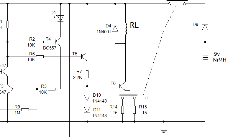 Relay driver
Driving the relay for the battery supply9V from the battery supply is provided by a relay and an NiMH rechargeable battery. When the mains power is connected diode D9 is reverse biased so the battery is not used. The relay driver circuit T5 and T6 is powered from the 12V supply and because the output from the delay circuit is held low both T5 and T6 are also switched on. Current is supplied to the coil of the relay which holds the battery supply contacts closed. The relay is held energized until the mains power is removed and the delay times out after which transistors T5 and T6 are turned off and the relay drops out to isolate the battery. In the delay time after mains power is removed the circuit is powered from the 9V battery allowing the relay to remain energized until timeout.
Using a relay with a variable power supply and constant currentRelays are generally specified in terms of the voltage that is intended to be applied to it to energize the coil and switch the contacts. I chose a relay with a 5V coil and I drive it with a constant current so that the changing supply voltage does not cause any problems. The constant current for the relay is generated by T5, R7, D10, D11, T6, R14 and R15. The two diodes provide a voltage reference of approximately 1.2V making the voltage on the emitter of T6 0.6V. The two 15 ohm resistors R14 and R15 are connected in parallel when the relay is de-energized making the effective resistance 7.5 Ω. The current in the relay coil is then 0.6/7.5 = 80mA. The resistance of the relay coil is approximately 60 Ω so the voltage across it would be 0.08 * 60 = 4.8V. To save power drain from the battery during the delay time I used a little trick. It takes a lot more current to switch a relay on than it does to hold it there so I've connected R14 and R15 to the normally closed side of one of the poles of the relay contacts. When the coil energizes and the contacts switch one of the resistors drops out of the circuit which halves the current supplied to the relay.
Protecting the driver circuit from spikes and overheatingYou might be wondering what the purpose of D4 across the relay coil is. It is connected reverse biased so it has no effect while the relay is energized. When the transistor T6 switches off however and the magnetic field in the relay collapses it produces a large spike of current in the opposite direction of flow. If it were not for D4 short circuiting this negative spike it could damage the transistor T6. The driver transistor T6 will generate a little heat. I used a small power transistor which gets warm to the touch so I bolted a small piece of metal to it to act as a heat sink. The heat sink isn't strictly necessary but I feel happier when things don't get too hot. The power dissipation in the power transistor will be greatest when running from the 12V supply which is most of the time. The voltage across the transistor will be approximately 9V with a current of 40mA. The power that will be dissipated by the transistor is therefore 9 * 0.04 = 360 mW. Just over a third of a watt. Well within the parameters of a power transistor but enough to make it get warm.
<< Previous
First
2
3
4
Last
Next >>
Automatic Power Off Shutdown For Raspberry Pi Power Off Delay Circuit Relay Driver Circuit Power Failure Detection Circuit DCDC Buck Converter |
| Now subscribe to our newsletter and don't miss a thing |
|
|

You should assume that there is an affiliate relationship and/or another material connection to the providers of goods and services linked to on this page and that we may be compensated when you purchase from a provider. Homediyelectronics.com is a participant in the Amazon Services LLC Associates Program and the Amazon EU Associates Programme, an affiliate advertising program designed to provide a means for sites to earn advertising fees by advertising and linking to amazon.com and amazon.co.uk.
Copyright © 2013 - 2024 homediyelectronics.com |
Legal |
Contact me |
Feed |
Google |
Site Map
Comments (1)
Add Comment