

How To Measure Output Impedance The Easy Way
Using an oscilloscope to measure output impedance

You've seen it written down most likely as part of the specifications of a signal generator or an audio amplifier. In fact just about any circuit that has a defined signal output will have an output impedance. So what is it? The symbol for impedance is 'Z' and the short answer is that impedance is frequency dependant resistance. This isn't strictly true in the technical sense but it's close enough for this discussion. Impedance rather than resistance is used in the context of AC signals where circuits inevitably consist of capacitive and inductive components as well as resistance. If you search the Internet for explanations of impedance then you might get frightened by all the talk about reactance, imaginary and complex numbers followed by some fancy vector mathematics. It all gets very complicated very quickly. Do you need to know all this? If you want to become an expert then yes you do but I'm going to stick to my simple definition of "frequency dependant resistance". It's even measured in Ohms Ω so it's quite easy to think of it that way. So now that we have a very simple definition of impedance how do you measure output impedance? Well there are several ways to do it and not all of them will work all of the time but in general the simple method that I'm going to describe will do the job for you.
Measuring the output impedance of the sound card oscilloscope signal generator Output impedance measurement circuit One of the most common reasons for measuring output impedance is to determine the characteristics of test equipment such as a signal generator. In my book Sound Card Oscilloscope: Build Better Electronics Projects I include a signal generator as part of the project so I'm going to measure the output impedance of this device. You can apply this same technique to any circuit that generates an AC output. 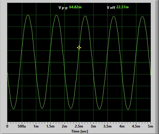 Open circuit generator output Impedance can not be measured using steady direct current signals so set the signal generator to produce a sine wave of 1kHz. Using an oscilloscope, measure the peak to peak amplitude of the voltage signal. You can use any oscilloscope to do this but I'm going to use my sound card oscilloscope because it's easy to use and take screenshots for this article. One thing that I should mention here is that all oscilloscopes have an input impedance which can in some circumstances, significantly modify the signal that you are trying to measure. This input impedance can be thought of a resistor across the load. Most oscilloscopes have an input impedance greater than 1MΩ. The sound card oscilloscope has an input impedance of 470kΩ. The input impedance of your measuring equipment must always be born in mind and ideally it should be significantly higher than the impedance of the circuit under test. The signal generator under test here has an output impedance of around 1kΩ so adding a 470kΩ oscilloscope should not pose a great problem. The next step is to select a suitable resistor to connect to the generator output and use as a 'load'. If you were a professional engineer you might have a resistor box handy. A resistor box is a piece of test gear that allows you to create accurate resistance values by dialing it in on its switches. Having said that, I'm a professional engineer and I've never owned or can remember even using one so it isn't an essential piece of gear. At least not for this tutorial. You want to choose a resistance that is roughly equal to the output impedance of the unit you are testing. But you don't know what that impedance is yet so choose something safe like a 1kΩ and connect it across the output of the generator. Using your oscilloscope, observe the peak to peak amplitude. The voltage should have dropped. If it has dropped below half of what it was without the resistor then it is too low a value. If it is above half the original then the load value resistance is too high. Adjust your load resistance value to reduce the output to roughly half of its original amplitude and measure the peak to peak voltage on your scope. 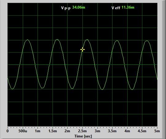 Generator output on load The next thing to do is to use a multimeter set to Ω and measure accurately the resistance of the load resistor that you ended up with. You may only have 10% tolerance resistors available so an accurate measurement may make a difference to the calculations. My load ended up as a 1kΩ resistor which measured 1026Ω When the voltage output amplitude of the generator is exactly half of what it is when the load is removed then the output impedance is equal to the load resistance. If you have reduced the output to roughly half and you only need an approximate measurement then you are done. If you want a more accurate determination then apply the formula below.
Z = (A1*RL/A2) - RL Substituting my values for the load resistance and the peak to peak voltage readings from the scope displays:
Z = (64.82 * 1026/34.06) - 1026 Note that the voltages measured do not have to be absolute readings. Only their relative magnitude is important. In this instance I knew that the output resistance of the sound card signal generator should be equal to the collector resistor of the output transistor in the circuit which is supposed to be 1kΩ. With this is mind I took the top off the calibrator box and measured the resistor with a multimenter. It read 980Ω which is about 5% different to the calculated value. |
| Now subscribe to our newsletter and don't miss a thing |
|
|

You should assume that there is an affiliate relationship and/or another material connection to the providers of goods and services linked to on this page and that we may be compensated when you purchase from a provider. Homediyelectronics.com is a participant in the Amazon Services LLC Associates Program and the Amazon EU Associates Programme, an affiliate advertising program designed to provide a means for sites to earn advertising fees by advertising and linking to amazon.com and amazon.co.uk.
Copyright © 2013 - 2024 homediyelectronics.com |
Legal |
Contact me |
Feed |
Google |
Site Map
Comments (2)
Add Comment