|
Circuit Diagram For The Pro-Mini Programmer Shield
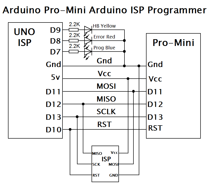
The Circuit diagram for the UNO Pro-Mini shield is shown above. It isn't difficult to wire up if you just want to do a quick programming job but it isn't nearly as convenient as building it onto a shield.
What's on the shield?
As I was building a shield I decided to equip it with a socket to accommodate the Pro-Mini and also an ISP connector. The ISP connector allows you to use the UNO/shield combination as a conventional Arduino ISP. The Pro-Mini socket can program a Pro-Mini by plugging it into the shield. If you are building a gadget using the Pro-Mini you might build in an ISP connector but if you are planning to make many of them then you might not want to do that for cost or space reasons.
Circuit description
Programming an Arduino makes use of the SPI interface so the MISO, MOSI and SCK terminals from the UNO are connected directly to the same pins on the Pro-Mini. The Pro-Mini needs some power so the 5v and Gnd from the Uno are connected to Vcc and Gnd on the Pro-Mini. The last signal that is needed is a reset. This is generated by the UNO's digital IO pin D10 and connected to the reset pin of the Pro-mini.
Indicator LEDs
The ArduinoISP example in the IDE provides for three indicator LEDs. A heartbeat LED pulsates gently to show that the programmer is running. An error LED glows when... well when there is an error of course and a programming LED which flashes during the programming process.
I used a yellow LED for the heartbeat, red for error and blue for the programming LED. You can use whatever colours you want.
The layout for the copper strip board is shown on the Shield Layout page.
| 


Comments
No comments yet.Add Comment