


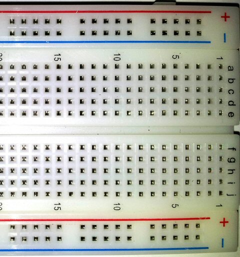
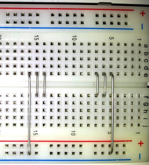
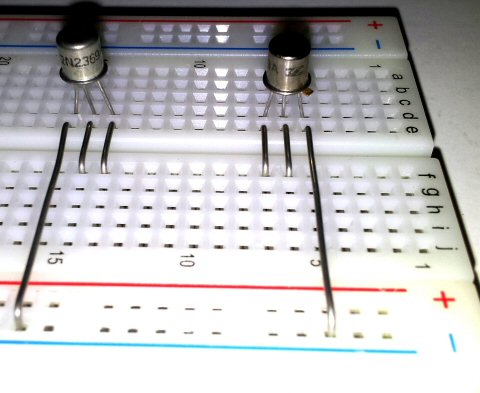
Building The Astable Multivibrator Part 1
Building The Astable Multivibrator LED Flasher
| |||||
| Now subscribe to our newsletter and don't miss a thing | |||||
|
|


You should assume that there is an affiliate relationship and/or another material connection to the providers of goods and services linked to on this page and that we may be compensated when you purchase from a provider. Homediyelectronics.com is a participant in the Amazon Services LLC Associates Program and the Amazon EU Associates Programme, an affiliate advertising program designed to provide a means for sites to earn advertising fees by advertising and linking to amazon.com and amazon.co.uk.
Copyright © 2013 - 2026 homediyelectronics.com |
Legal |
Contact me |
Feed |
Google |
Site Map
Comments (5)
Add Comment