|
|
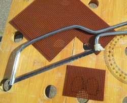
Use a small saw to cut your perforated board to size. Before you do this you should take your components and lay them onto the board in the positions you want them and then mark out the edges of the board allowing enough space for all components and connections.
My board measured approximately 60mm (2.4inch) x 48mm (1.9inch). Remember it is better to overestimate the size you need rather than cut the board too small to fit the parts onto.
|
|
|
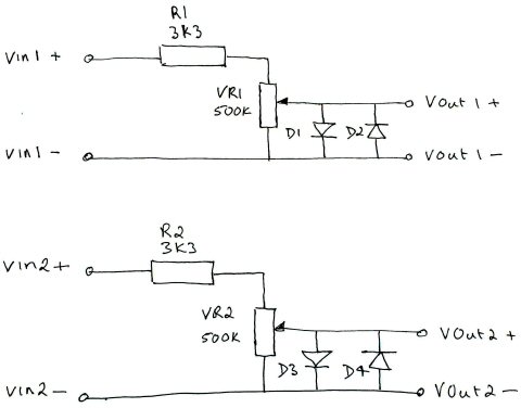
Remind yourself of the circuit diagram. The circuit is simple and in two identical parts.
|
|
|
It will be helpful at this point to draw a sketch of what you want the final PC scope probe to look like with the input and output connections marked on it.
|
|
|
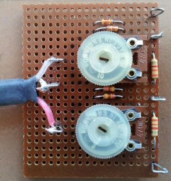
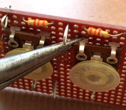
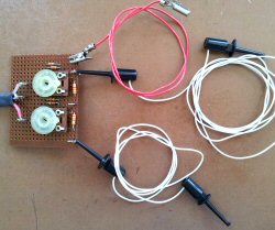
This is the top side of my finished scope probe board. Note that each of the two pairs of diodes are connected top to toe in parallel.
|
|
|
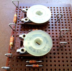
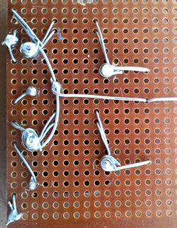
This is a slightly different view of the top side of my board showing how I mounted the home made connection posts. If you choose to use the alternative method of making the posts then be sure to allow extra room for the additional hole that each post will take up.
|
|
|
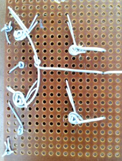
If you can you should make all the connections on the underside of your board by wrapping the leads together. When you have finished carefully inspect the wiring and compare it against the circuit diagram. It is much easier to correct any errors at this stage before you solder all the connections.
|
|
|
Before you start soldering please bear in mind that your components will get hot during this process and that electronic parts can be damaged by excessive heat. This is a general problem with building electronic projects so it's a good idea to try and minimize the time that you apply the hot soldering iron. In some instances you can apply a heat sink to the component leads to conduct some of the heat away from the device. Semiconductor devices like transistors, diodes and integrated circuits are very susceptible to heat damage.
|
|
|
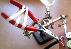
I have a simple technique that works well for me. I use a pair of Long nose pliers to grip the component lead between the device and the point where you apply the heat. The problem with this is that you end up needing 3 hands to hold the pliers in place while you apply the solder. Placing a strong elastic band around the handle of the pliers should hold them clamped onto the lead long enough for you to solder it.
|
|
|
Solder all the connections. If you are not sure about how to solder then be sure to go through the soldering tutorial Soldering Is Easy before you start.
|
|
|
Take your audio lead and cut off one of the 3.5mm jack plugs. Strip the wires slip a small length of heat shrink tubing on to keep the end tidy and connect the two inner cores to Vout1 and Vout2 and the outer braid of the wire to the common connection as shown.
|
|
|
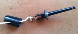
For your input connections you can either use crocodile clips or small probe clips. I like these small clips as they are easy to connect up and to use.
|
|
|
It's best to use flexible wire for your probe cables. Push it through the hole in the clip, strip the insulation, solder the connection and snap the two halves of the clip back together.
|
|
|
This is how my final PC scope probe looks. It's not very pretty but it works. On the next page I show you how to get the software up and running with your probe.
|


Comments (50)
But cant find the link ( lin adress ? ) tocharge on the computer ( for simulating the 2 channels of a osciloscope ).?
Could you answersto my mail adress ?
Thank
Your
Bes t regards
Patrick Montpellier France
1. To which port of my do I connect the output probe to? headphones or microphone or line-in?
2. For my experiments, I may have to operate around a voltage of 15 to 22 volts. Will this pose a threat to my sound card?
I want to make this oscilloscope to test sensors and wiring on my car, but the cars voltage is between 12v and 14.4v.
Will this work for me?
Or, are there any changes that I can make to the design so that it will cater to my needs?Thank you.
Can I use the above PC Sound Card based oscilloscope to display the ECHO & TRIG waves of an Ultrasonic Sensor Module(HC SR-04) ?
I see under your other project(s) on this website you are using HC SR-04; So I assume that you are better aware of the details for the same.Regards,
Saurabh
it seems to work right. I have been meaning to ask what the difference is between the poly box ones you use and the ones I used.
still much to learn, but having a great time with your book so far. now on to building the cali/generator. thanks Steve
Steve
Steve
Thank you
i have a doubt thoughHow and why are we selecting a 3.3 k ohm and a 470k pot?
another point that i was wondering about is how does the two zener diodes work.P.S. im a noob in electronics :P
What is a 3K3 resistor, do you mean a
3K Ohm resistor. excellent article
Add Comment