


PC Sound Card Oscilloscope Circuit Diagram
Simple Oscilloscope Circuit SchematicThe book: Sound Card Oscilloscope - Build Better Electronic Projects contains a slightly better circuit for the probe plus additional circuitry for calibration and a signal generator. These are all valuable additions to your tool kit. If you want to buy a cheap but inexpensive USB based oscilloscope then you could do worse than the Hantek 6022BE USB scope.
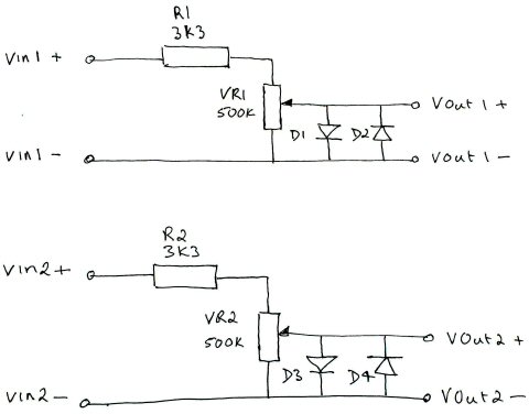
The PC probe circuit could hardly be simpler. Each channel consists of an input resistor (R1/R2) to protect the overload diodes (D1-D4). The signal is fed through the input resistor to the potentiometer (VR1/VR2) and then out again to the PC sound card mic or line in input. The diode pairs D1/D2 and D3/D4 are connected head to toe to limit the microphone input to approximately 500mV. This should protect your PC from any damage providing that you do not attempt to use the probe on signals greater than 10-12 volts. The input resistor together with the potentiometer convert the signal you want to examine to a level that does not overload the sound card input circuitry. If you allow signals that are too large to pass through then you will see the signals distort on the screen.
|
| Now subscribe to our newsletter and don't miss a thing |
|
|

You should assume that there is an affiliate relationship and/or another material connection to the providers of goods and services linked to on this page and that we may be compensated when you purchase from a provider. Homediyelectronics.com is a participant in the Amazon Services LLC Associates Program and the Amazon EU Associates Programme, an affiliate advertising program designed to provide a means for sites to earn advertising fees by advertising and linking to amazon.com and amazon.co.uk.
Copyright © 2013 - 2026 homediyelectronics.com |
Legal |
Contact me |
Feed |
Google |
Site Map
Comments (50)
Steve
I want to make this oscilloscope to test sensors and wiring on my car, but the cars voltage is between 12v and 14.4v.
Will this work for me?
Or, are there any changes that I can make to the design so that it will cater to my needs?Thank you.
1. To which port of my do I connect the output probe to? headphones or microphone or line-in?
2. For my experiments, I may have to operate around a voltage of 15 to 22 volts. Will this pose a threat to my sound card?
But cant find the link ( lin adress ? ) tocharge on the computer ( for simulating the 2 channels of a osciloscope ).?
Could you answersto my mail adress ?
Thank
Your
Bes t regards
Patrick Montpellier France
What is a 3K3 resistor, do you mean a
3K Ohm resistor. excellent article
i have a doubt thoughHow and why are we selecting a 3.3 k ohm and a 470k pot?
another point that i was wondering about is how does the two zener diodes work.P.S. im a noob in electronics :P
Thank you
Steve
it seems to work right. I have been meaning to ask what the difference is between the poly box ones you use and the ones I used.
still much to learn, but having a great time with your book so far. now on to building the cali/generator. thanks Steve
Can I use the above PC Sound Card based oscilloscope to display the ECHO & TRIG waves of an Ultrasonic Sensor Module(HC SR-04) ?
I see under your other project(s) on this website you are using HC SR-04; So I assume that you are better aware of the details for the same.Regards,
Saurabh
Add Comment