


PC Sound Card Probe Test Points
Building the Sound Card OscilloscopeBefore you build the project here check out my book: Sound Card Oscilloscope - Build Better Electronic Projects. It contains a slightly better circuit for the probe plus additional circuitry for calibration and a signal generator. If you want to buy a cheap but inexpensive USB based oscilloscope then you could do worse than the Hantek 6022BE USB scope.
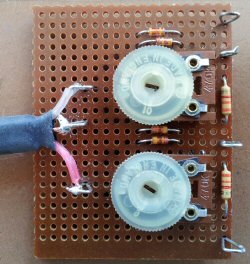
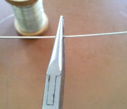
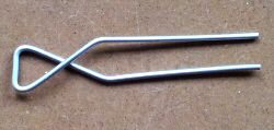
This is a very simple circuit that can easily be built on a small piece of perforated matrix board. I used a piece of board that had no copper at all but you can use one that has isolated copper pads around each hole just as easily. The way that you build your probe will depend on what type of potentiometer you decide to use. I had some large trimmer variable resistors in amongst my junk but you can use any type of trimpot or panel mount controls just as easily. Each of the two channel circuits are identical and can be built on the same board next to each other as in the picture. Making test point posts Input and output cables should be attached to wire posts on the edge of the board for convenience. You can buy proper posts that fit into the holes in perforated board if you want to. I have some of these test point posts and frankly I think that they are more trouble than they are worth. I would rather make my own and this is how you do it.
| ||||||||||||||
| Now subscribe to our newsletter and don't miss a thing | ||||||||||||||
|
|


You should assume that there is an affiliate relationship and/or another material connection to the providers of goods and services linked to on this page and that we may be compensated when you purchase from a provider. Homediyelectronics.com is a participant in the Amazon Services LLC Associates Program and the Amazon EU Associates Programme, an affiliate advertising program designed to provide a means for sites to earn advertising fees by advertising and linking to amazon.com and amazon.co.uk.
Copyright © 2013 - 2026 homediyelectronics.com |
Legal |
Contact me |
Feed |
Google |
Site Map
Comments (50)
But cant find the link ( lin adress ? ) tocharge on the computer ( for simulating the 2 channels of a osciloscope ).?
Could you answersto my mail adress ?
Thank
Your
Bes t regards
Patrick Montpellier France
1. To which port of my do I connect the output probe to? headphones or microphone or line-in?
2. For my experiments, I may have to operate around a voltage of 15 to 22 volts. Will this pose a threat to my sound card?
I want to make this oscilloscope to test sensors and wiring on my car, but the cars voltage is between 12v and 14.4v.
Will this work for me?
Or, are there any changes that I can make to the design so that it will cater to my needs?Thank you.
Can I use the above PC Sound Card based oscilloscope to display the ECHO & TRIG waves of an Ultrasonic Sensor Module(HC SR-04) ?
I see under your other project(s) on this website you are using HC SR-04; So I assume that you are better aware of the details for the same.Regards,
Saurabh
it seems to work right. I have been meaning to ask what the difference is between the poly box ones you use and the ones I used.
still much to learn, but having a great time with your book so far. now on to building the cali/generator. thanks Steve
Steve
Steve
Thank you
i have a doubt thoughHow and why are we selecting a 3.3 k ohm and a 470k pot?
another point that i was wondering about is how does the two zener diodes work.P.S. im a noob in electronics :P
What is a 3K3 resistor, do you mean a
3K Ohm resistor. excellent article
Add Comment