


Long Time Delays With A 555 Chip
Long time delays with a 555 integrated circuit
Battery powered data loggerI'm working on a project to allow me to wirelesssly measure and log the temperatures in a building. I want to build an accurate picture of how the temperature varies from room to room and over time. The information gained can then be used to optimise the heating system. I'm looking at various options to accomplish this from simple dumb sensors with a transmitter or a cheap microcontroller like the Arduino to full wifi enabled microcomputer systems like the Raspberry Pi. Whatever I choose for the remote hardware it will need to be cheap to produce and low power enough to operate for several days at least on battery. I'm going to take advantage of the fact that I only need to record temperature every 10 minutes or more to minimise the average current consumption. To do this I need a low power, long time delay circuit to wake up the logger at regular intervals, take readings and transmit the data to a base station.
The 555 - A simple timer chipThe obvious place to look first when in need of a timing circuit is the 555 timer chip. It's been aroound almost as long as I can remember but it still manages to impress me with it's capabilities. The standard 555 IC has a low power consumption. I measured the current that one in-circuit 555 used at 8mA. This doesn't sound much but if you run the device off a 2000 mAH battery then it can only be expected to work for 10 days. This may be enough but this has to be put together with the power used by the datalogger when it's turned on for say 1 minute out of 10. If the logger takes 200mA when powered up then this is equivalent to 20mA continuous. With an average current of 28mA the battery will only last for less than 3 days. If the timer power could be reduced to zero then the battery would last 30% longer. The standard 555 chip takes 8mA but there is a low power CMOS version of the 555 which requires significantly less power to operate. I don't have any low power versions but I do have a standard one so I'm going to start testing that until I can get my hands on a low power version.
555 delay circuitsThe 555 can be used in a number of different ways to produce square waves, pulses or simple one shot timing. I need a one shot timer that can energise the datalogger after a delay and be reset by the datalogger after it has performed the task. I began by testing the 555 in some conventional circuits and I was easily able to achieve repeatable delays of several minutes. I want longer delays. I want to have a delay that I can set from 10 minutes to a few hours. I could use a 555 to generate a 1 second or slower pulse which I then feed into a counter to produce long and accurate delays but that seemed a bit of overkill. That was when I found a simple variation on the basic circuit. I don't need the delay to be particularly accurate because I will need to log the time of the reading anyway. It doesn't matter whether I take readings every 8 minutes of every 12 minutes apart from the impact on the battery life of course. Anyway the circuit above seems to do just nicely.
Testing the standard 555I tested the above circuit with 3 values of resistor RT. Here are the results:
I'm sure that this circuit will do even longer time delays stretching into days if required but once every 90 minutes is the longest I shall need for my datalogger. Now where is that low power version? |
| Now subscribe to our newsletter and don't miss a thing |
|
|

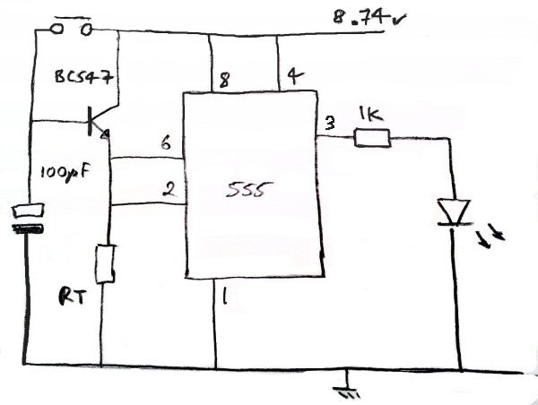 Circuit for 555 long time delay
You should assume that there is an affiliate relationship and/or another material connection to the providers of goods and services linked to on this page and that we may be compensated when you purchase from a provider. Homediyelectronics.com is a participant in the Amazon Services LLC Associates Program and the Amazon EU Associates Programme, an affiliate advertising program designed to provide a means for sites to earn advertising fees by advertising and linking to amazon.com and amazon.co.uk.
Copyright © 2013 - 2026 homediyelectronics.com |
Legal |
Contact me |
Feed |
Google |
Site Map
Comments (18)
Used pnp transister Bc557 connected to out put of pin 3 with relay drive. I need one clarification. One end of the capacitor is connected to base of transistor Bc547. Pl clarify how discharge of capacitor is taking?
Used pnp transister Bc557 connected to out put of pin 3 with relay drive. I need one clarification. One end of the capacitor is connected to base of transistor Bc547. Pl clarify how discharge of capacitor is taking?
T=1.1 X R X C
R in Ohm, C in Farad, T in Sec
8 hours = 8 X 3600 sec = 28800 Sec
Do not use higher value of R (2.2MOhm and more)
The quality of the C is very important(Lower leakage, more accurate timing)
Thanks for your guide. I'm looking for a long timer with a 1 second pulse at the end to start a washing machine. Is it likely that I could extend the delay to around 4-5 hours using your method above?
Thanks.
Add Comment