


Arduino Programming the HC-SR04 Project Circuit Diagram
Circuit diagram for the Arduino HC-SR04 programming projectIf you want to be able to examine the waveforms produced by this and other projects then get a copy of my book: Sound Card Oscilloscope and build yourself some very capable test gear. 
Distance finder circuit diagram See the full range of Arduino products 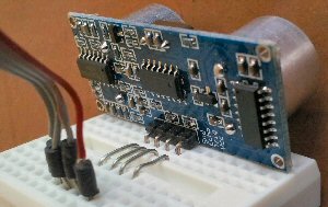
You just need 4 jumper wires to connect this up. I used an old piece of ribbon cable that I had lying around. I stripped off the ends, soldered half an inch of solid wire on the end then covered the joint with some sleeving. It works well but it can be very tedious making the cables. By the time I had finished I told myself that I wasn't going to do that again and ordered up some ready made jumper cables to use next time. I used 4 solid wires to bridge the center gap in the breadboard and that's all you need to do. On the next page you can download the software that you need.
|
| Now subscribe to our newsletter and don't miss a thing |
|
|

You should assume that there is an affiliate relationship and/or another material connection to the providers of goods and services linked to on this page and that we may be compensated when you purchase from a provider. Homediyelectronics.com is a participant in the Amazon Services LLC Associates Program and the Amazon EU Associates Programme, an affiliate advertising program designed to provide a means for sites to earn advertising fees by advertising and linking to amazon.com and amazon.co.uk.
Copyright © 2013 - 2026 homediyelectronics.com |
Legal |
Contact me |
Feed |
Google |
Site Map
Comments (13)
is it possible that the only working pin for Echo signal is 2?
Why can't I put it on a random digital input, since the interrupt is generated by the timer?
Juan Alberto
for my lesson i need your code .
can you send it for me please.
i observe publisher's rights, and introduce your site to my friends.
Add Comment