Click here for a free subscription to "HDE" our site newsletter.

LED Bar Graph With Transistors


An 11 Element LED Bargraph


LED Bargraph built on a solderless breadboard Transistors drive eleven LEDs in an analog bar

There are a number of integrated circuits and modules available that are designed specifically for building led bar graph circuits but if your junk box looks anything like mine then you probably don't have one. What if you want to build a bar graph today and don't have the right chip?

I always have a small stock of transistors, diodes and resistors to hand just like most other hobbyists. We have them because they are easy to obtain, cheap as chips and useful for all kinds of things. So if I can build something out of these basic components then I can get the circuit working in an hour or two without waiting for an online order to arrive. Why don't you give this one a try.

Potentiometer for simulating input 
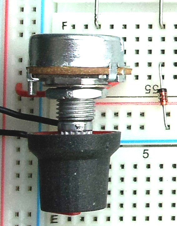
Potentiometer input simulator


To demonstrate the bargraph circuit you can use a potentiometer control. A 5kΩ or 10kΩ potentiometer can be wired across the input voltage reference to provide a variable input voltage to the bargraph. If you have a control with printed circuit board terminals like the one I used then the pins will probably fit into the breadboard without modification.

If the terminals on your potentiometer are too wide then you can file them down a little using a flat needle-file.


Now subscribe to our newsletter and don't miss a thing


Comments (5)

Topic: LED bar graph with transistors
Full StarFull StarFull StarFull StarHalf Star 4.5/5 (5)
Facebookdel.icio.usStumbleUponDiggGoogle+Twitter
Full StarFull StarFull StarFull StarFull Star
Wilame (Brazil) says...
Wow, its amazing. Congratulations for to share with us.
13th July 2020 5:40pm
Full StarFull StarFull StarFull StarEmpty Star
Harold Lacadie (US) says...
Works as advertised! However I could only get it to work is with a LM358 which is what the LM324 is based on. Really cool circuit!
26th June 2020 12:04am
Full StarFull StarFull StarFull StarEmpty Star
Derek Jacobsen (US) says...
Hi Tim, I tried building this circuit as a fun home project but am having some trouble getting it to work. Are the positive and negative ves the positive and negative terminals of one battery or two batteries with one connected negatively. Also im not sure how the physical hardware wiring of the potentiometer works. Any help you could give me would be much appreciated.
19th November 2019 7:58pm
Full StarFull StarFull StarFull StarEmpty Star
Tom (US) says...
As to the battery question, it looks like one nine volt battery with the + connected to the top (+) and the - connected to the ground which is marked -ve. Regarding the 10,000 ohm potentiometer question the typical potentiometer has three terminals. The center terminal is shown in the center and is connected to the hollow o by an arrow. This terminal is where the knob changes the resistance relative to the two other terminals. (I realize it has been years since this question was asked but this ... Read More
12th December 2023 11:45pm
Full StarFull StarFull StarFull StarFull Star
Tim Ralston (US) says...
Simply perfect! designs like these always save the day when you can pop it together right out of the parts box, especially if you need to knock together a last minute gadget. Being able to say "yes I can do that in a couple hours" vs a couple days, always keeps me employed.
Thank you, Thank you, Thank you, for your generous sharing.
Tim
20th April 2017 4:18am

Add Comment

* Required information
(will not be published)
 
Bold Italic Underline Strike Superscript Subscript Code PHP Code Quote Insert line Bullet list Numeric list Link Email Image Video
 
Smile Sad Huh Laugh Mad Tongue Crying Grin Wink Scared Cool Sleep Blush Unsure Shocked
Captcha
Refresh
 
Enter code:
 
Notify me of new comments via email.
 
Remember my form details on this computer.
 
I have read and understand the privacy policy. *
 
I have read and agree to the terms and conditions. *
 
Click here for a free subscription to "HDE" our site newsletter.